Electrical Circuit Basics

Merrian-Webster defines a Circuit as the complete path of an electric current including usually the source of electric energy. In order for energy to flow, there has to be a complete circuit.

In simpler terms, consider your light switch. When you flip the switch, it works because it is closing, or completing, an electrical circuit. When the switch is off, there is literally a gap in path, thus it is not a complete circuit, and there is no flow of energy from the source to the load, or the light bulb.

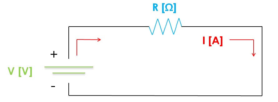
Every current contains three things: voltage, current and resistance.

* Voltage is the potential energy of an electric supply which pushes a current around from node to node. It is expressed in units called Volts [V], and is typically denoted with the variable "V" in electrical engineering.

* Current is the movement or flow of an electrical charge. It is expressed in units called Amps or Amperes [A], and is typically denoted with the variable "I" in electrical engineering.

* Resistance is the ability of a circuit to prevent the flow of the current. It is expressed in units called Ohms [Ω], and is typically denoted with the variable "R".

You could think about it in way of water flow, if its easier for you. In water flow, a pump is the source which provides the water pressure, much like a battery would provide the voltage. The pipe the water flows through is the resistence. The current is the rate at which the water flows.

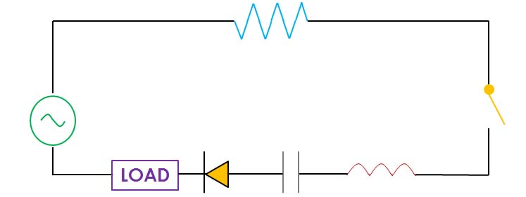
A circuit will typically have a load that uses some of the energy flowing through the circuit. There are many other components that can be a part of a circuit, all of which have different roles. Some of the more common components are:

* Switches connect and disconnect a circuit (or close and open it).

* Resistors lower the voltage and electrical current flowing within a circuit. They are used in DC circuits.

* Diodes dictate the direction of flow of the current. They can be used for many reasons, including being used to create alternating current from direct current. In the home-made solar panel tutorial, the diode is used to make sure that the current does not flow backwards, thus ensuring that the solar panel is always charging the load and not the other way around.

*Capacitors store electrostatic energy in an electrical field. They are usually used in AC circuits. They have many uses that deal with stabilizing the voltage and current of the power supply. They are also used to tune into specific radio frequencies.

*Inductors store energy in a magnetic field. They are usually used in AC circuits. They provide much the same purpose as the capacitor, but they just store a different kind of energy that is present.

You should notice that the graphic above shows a different symbol for the source than the previous one. This symbold indicates that the source is providing AC power instead of DC, meaning that the current travels in both directions.

On that note, we have mentioned that the capacitors and inductors are primarily used in AC circuits. You may have also noticed that they deal with electrostatic and magnetic fields. This is because the nature of current flow in AC circuits causes self induced "resistance" in the forms of magnetism and electrostatic energy. Because they are a different nature, the combination of capacitance and inductance is known as reactance. The combination of resistance and reactance is known as impedance. So in DC circuits, resistance alone acts against the current, where in AC circuits reactance is added to the mix and impedance acts against the current.

There are many other symbols and components you might see, but these were some of the basic ones. Also, there is much more to be said about AC and DC if you want to fully understand circuits. You can learn more on our tutorial about the difference between AC and DC. You'll also want to know about circuits in series and parallel. The information you've learned should be enough to get you going. Thanks for visiting and learn on!

More About Circuits
DIY Sustainable Solutions Tutorials